


Explain System Flow
Paste stages, inputs, equipment, or handoffs and create a visual that clarifies how the process moves.
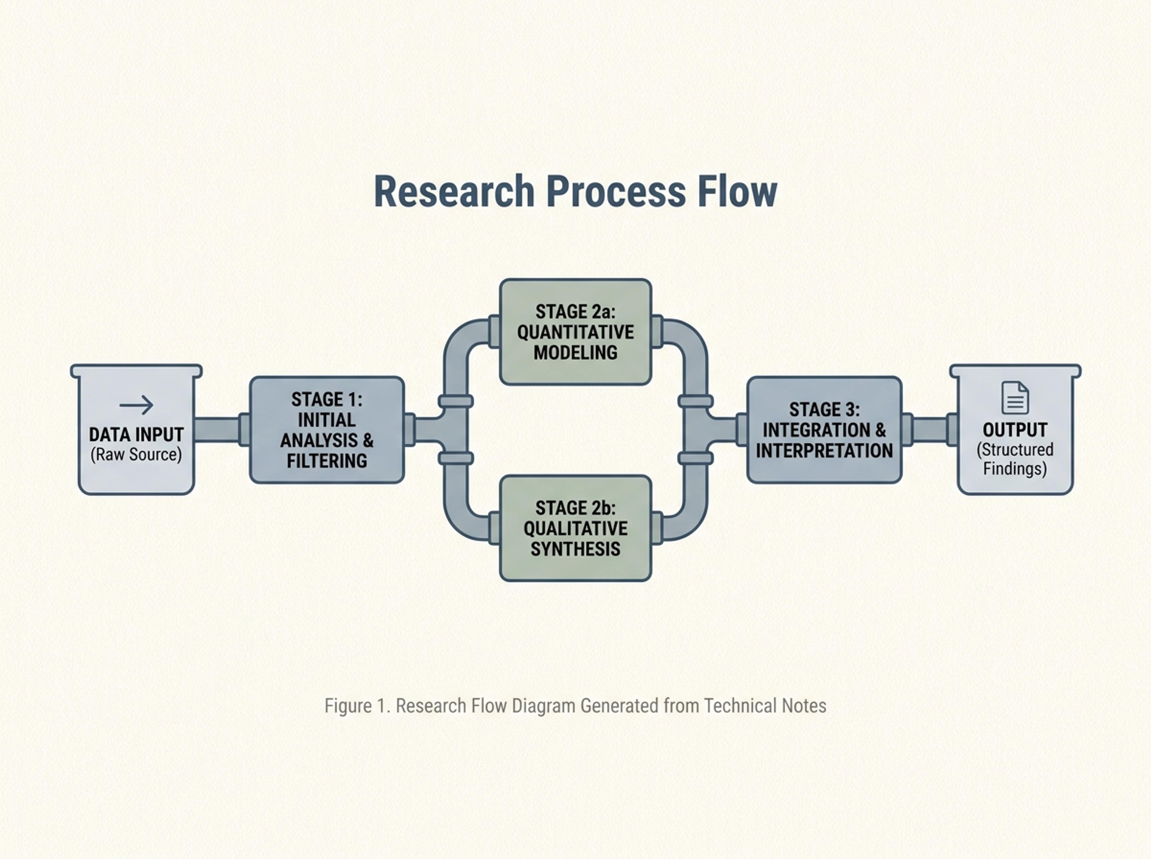
Drop in a P&ID description, technical spec, or system overview and Infograph composes a clean pipe process diagram with named units and flow direction.
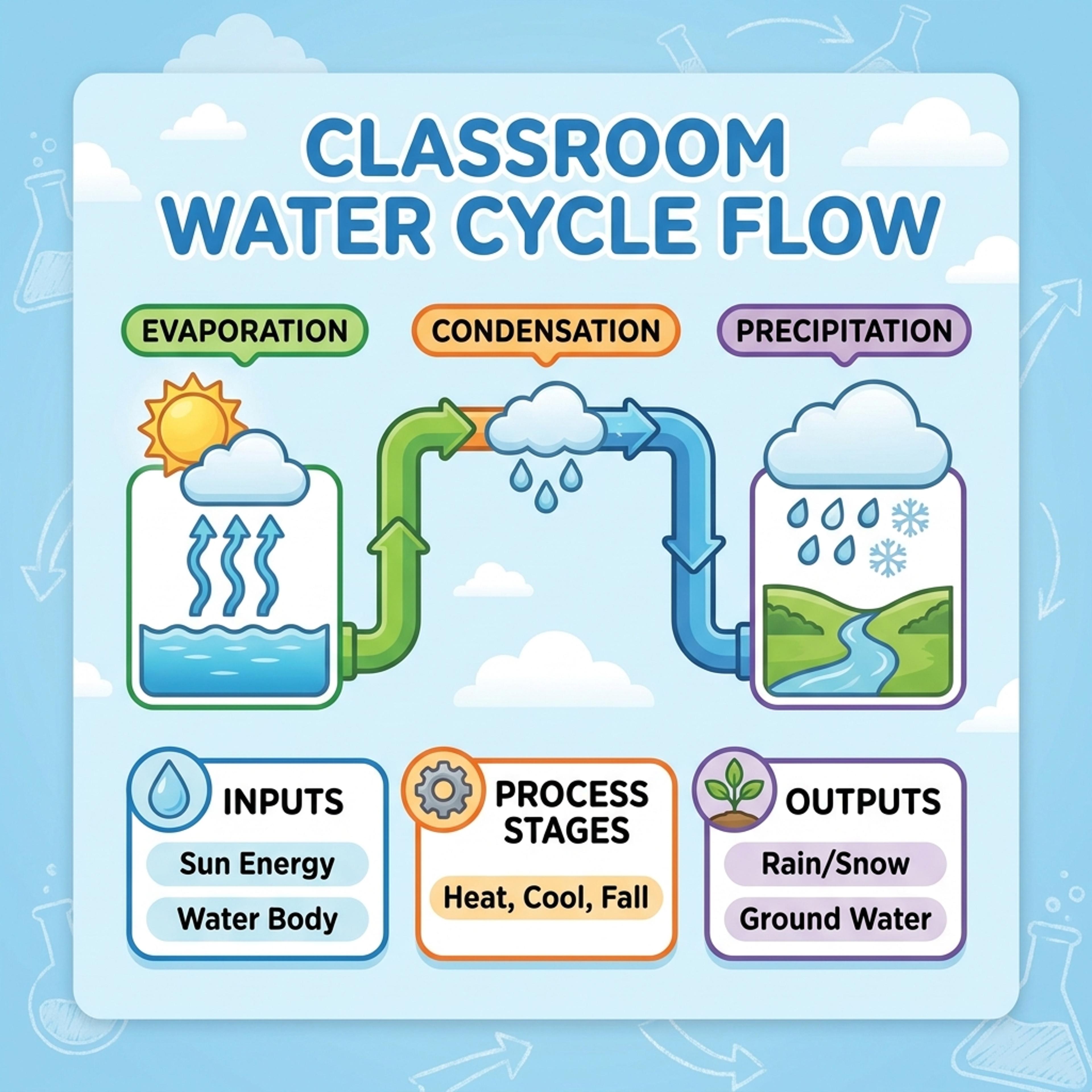
Drag and drop your paper, lab notes, lesson material, or document here or
A pipe process diagram shows how materials, information, energy, or decisions move through connected stages. It is useful for engineering specs, operations reviews, system explanations, classroom science, and any technical process that needs a clean visual path.
Start with process steps, system notes, inputs, outputs, or a technical brief and let Infograph organize flow direction, labels, branches, and callouts into a readable pipe process diagram.
Paste stages, inputs, equipment, or handoffs and create a visual that clarifies how the process moves.
Turn a K-12 STEM lesson into a colorful step-by-step process visual students can follow quickly.
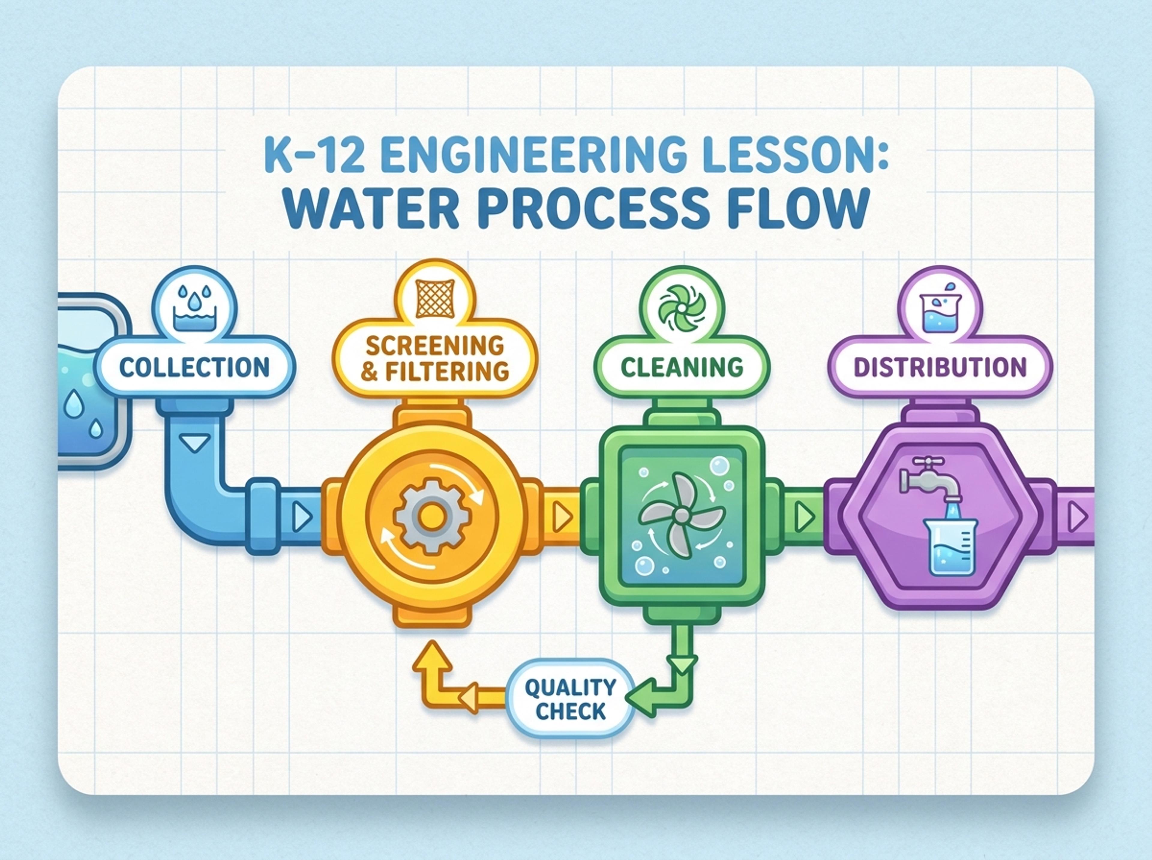
Convert engineering notes, requirements, or procedures into a structured visual for review and discussion.
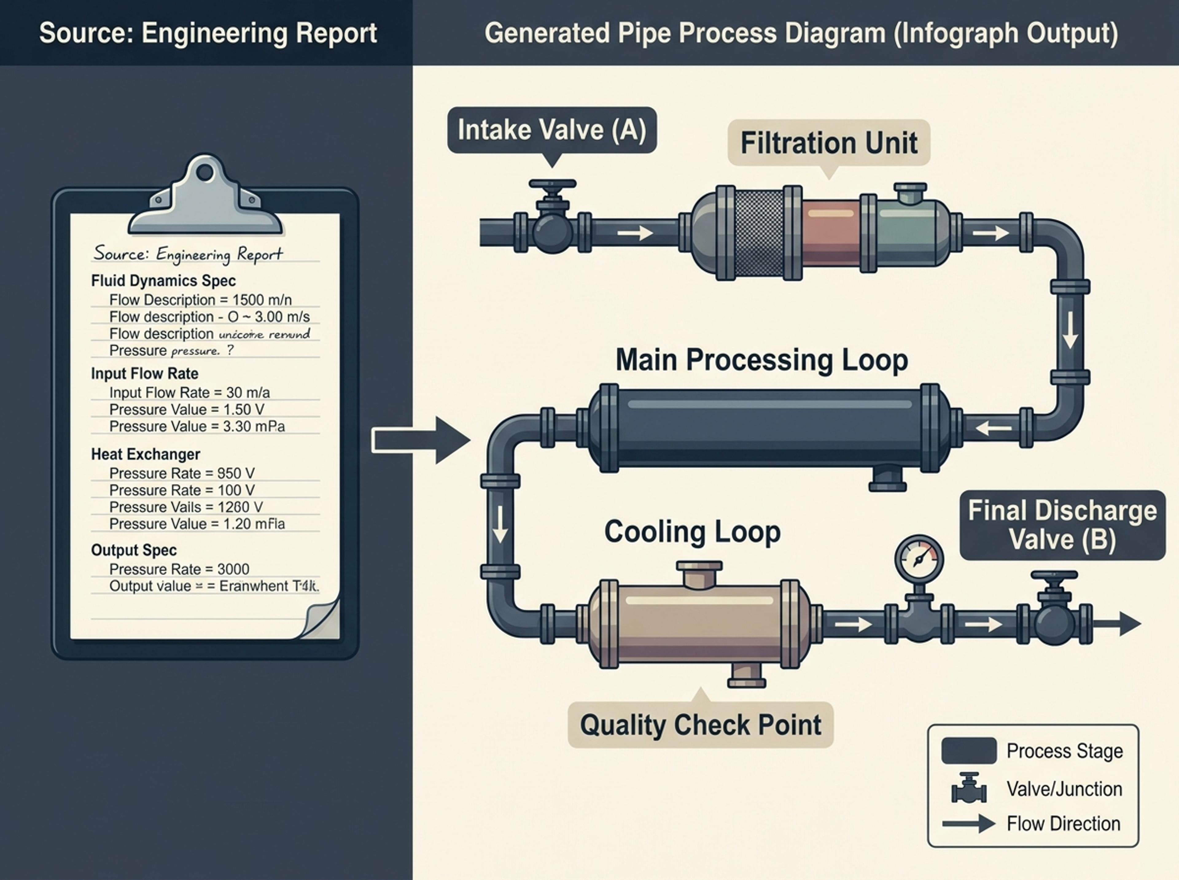
Drop in a technical spec, P&ID notes, or a paragraph describing the system. Engineering jargon is preserved exactly so labels stay precise.
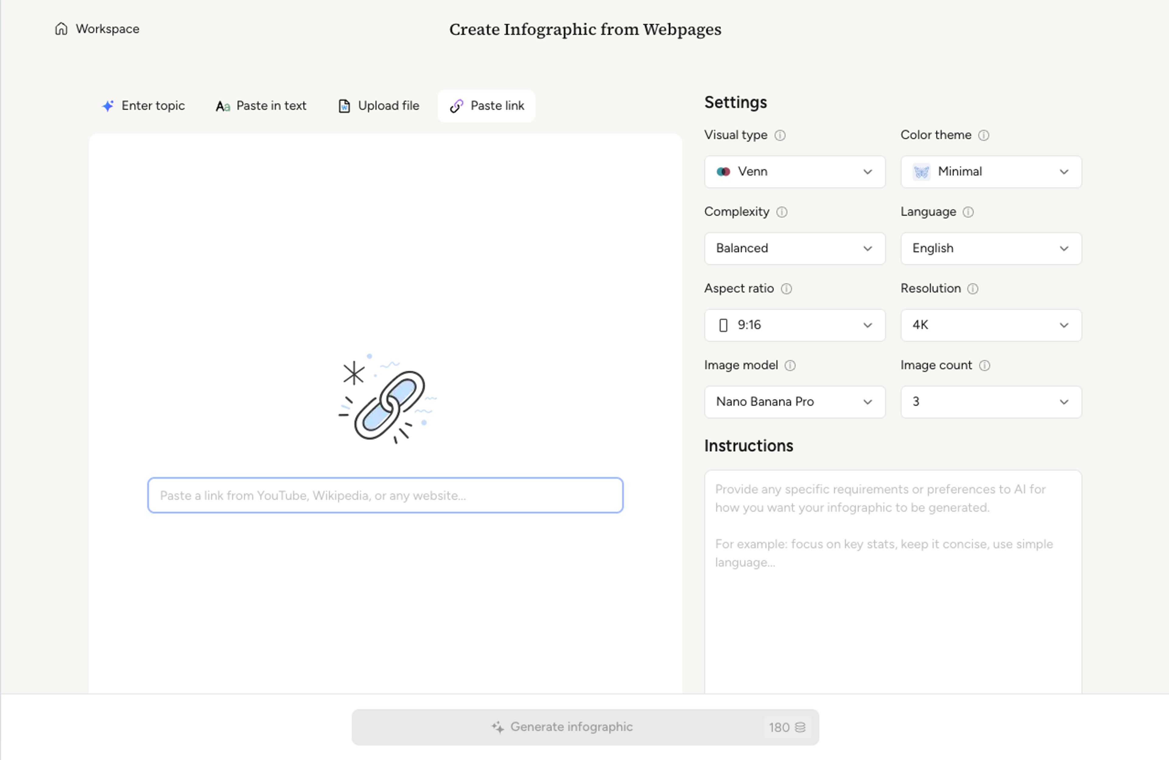
Set how many stages to render, whether the flow is linear or branching, and which valves, junctions, or units should appear as named nodes.
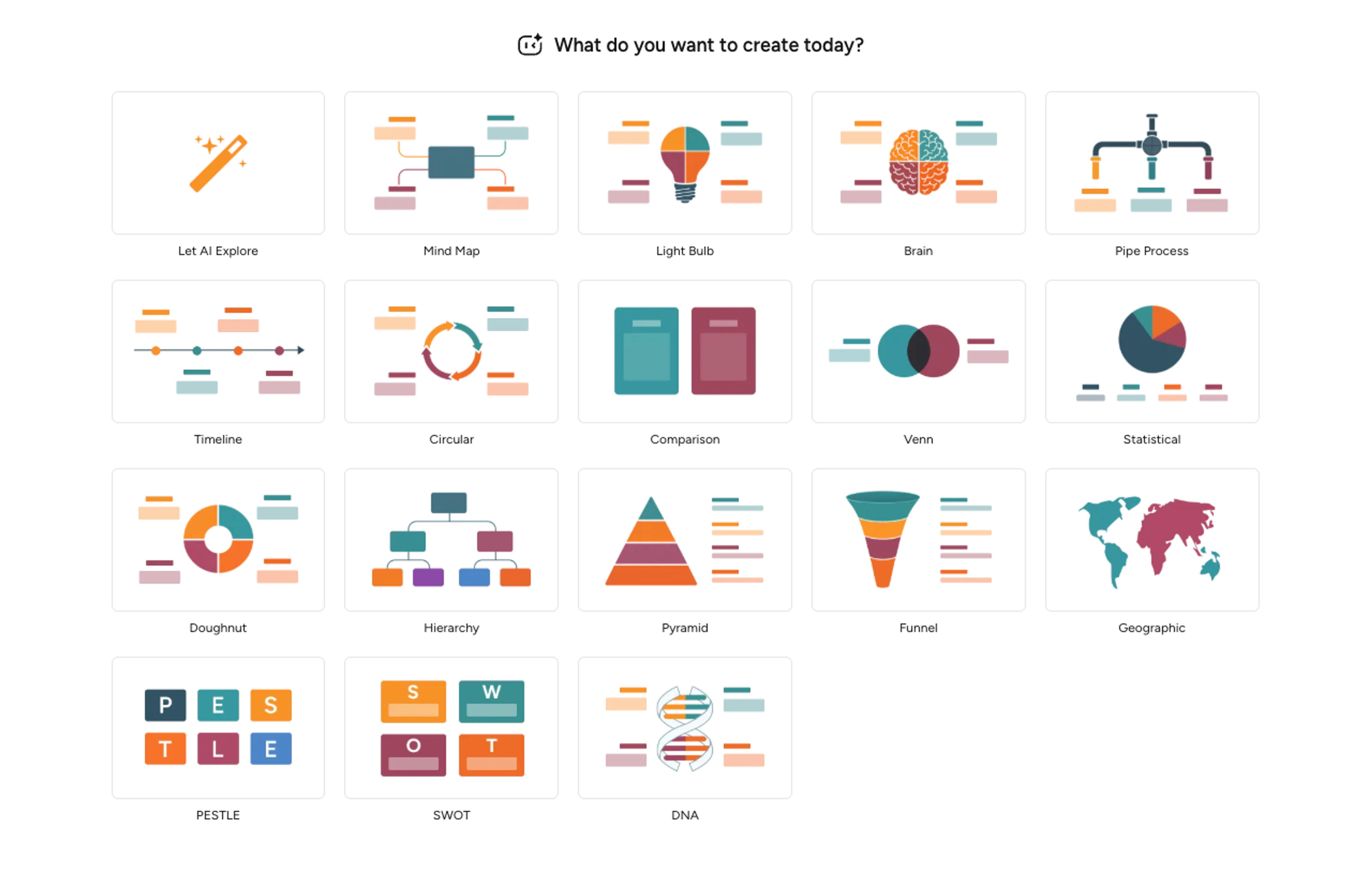
AI lays out each unit as a connected pipe segment, ordering inputs and outputs to match the source description and keeping consistent line weights.
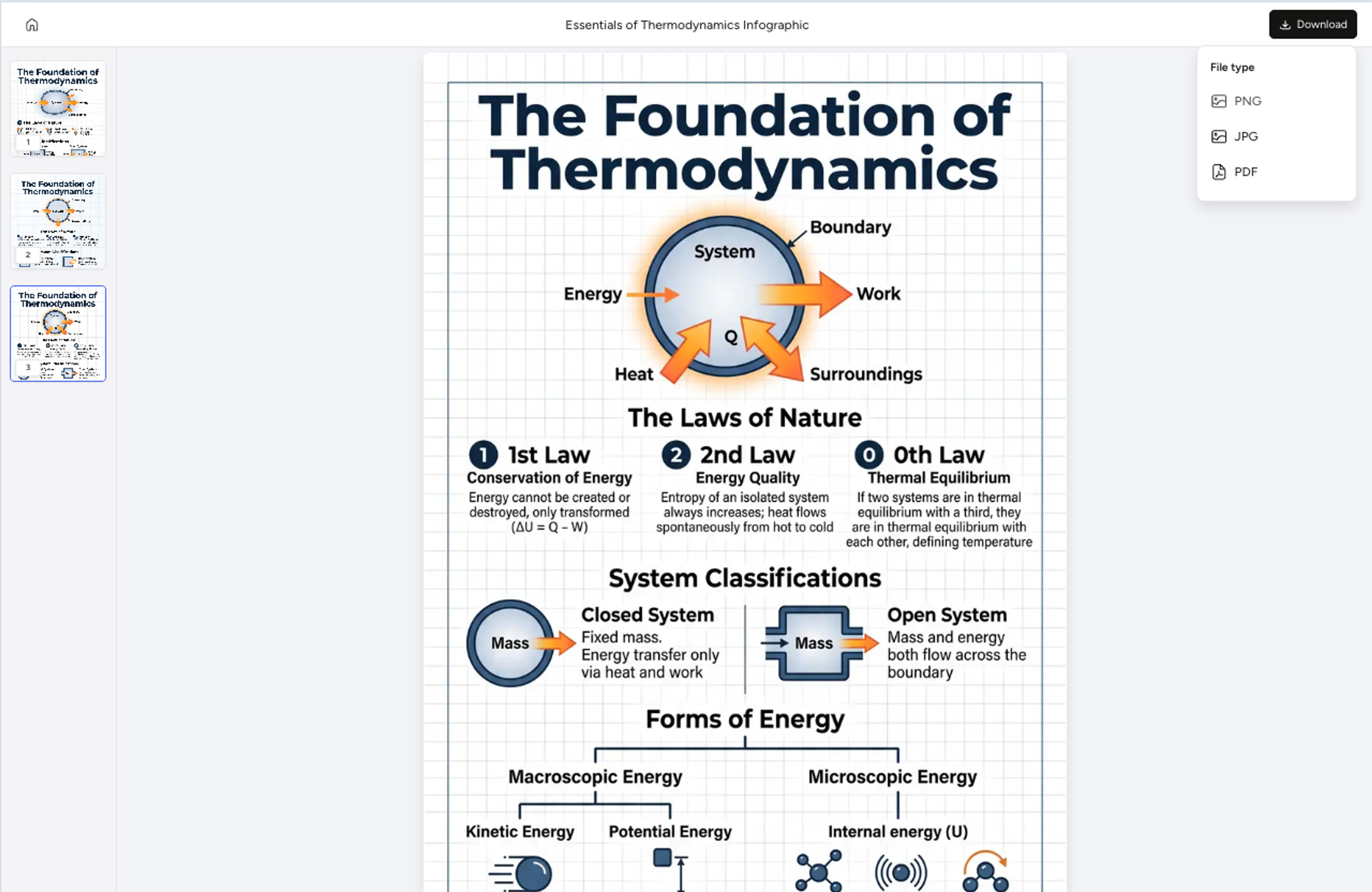
Adjust node labels, recolor segments by subsystem, and export the pipe process diagram as PNG, JPG, or PDF for engineering reports or training material.
Explore pipe process diagram results Infograph can create for operations, K-12 STEM, technical research, and process planning.
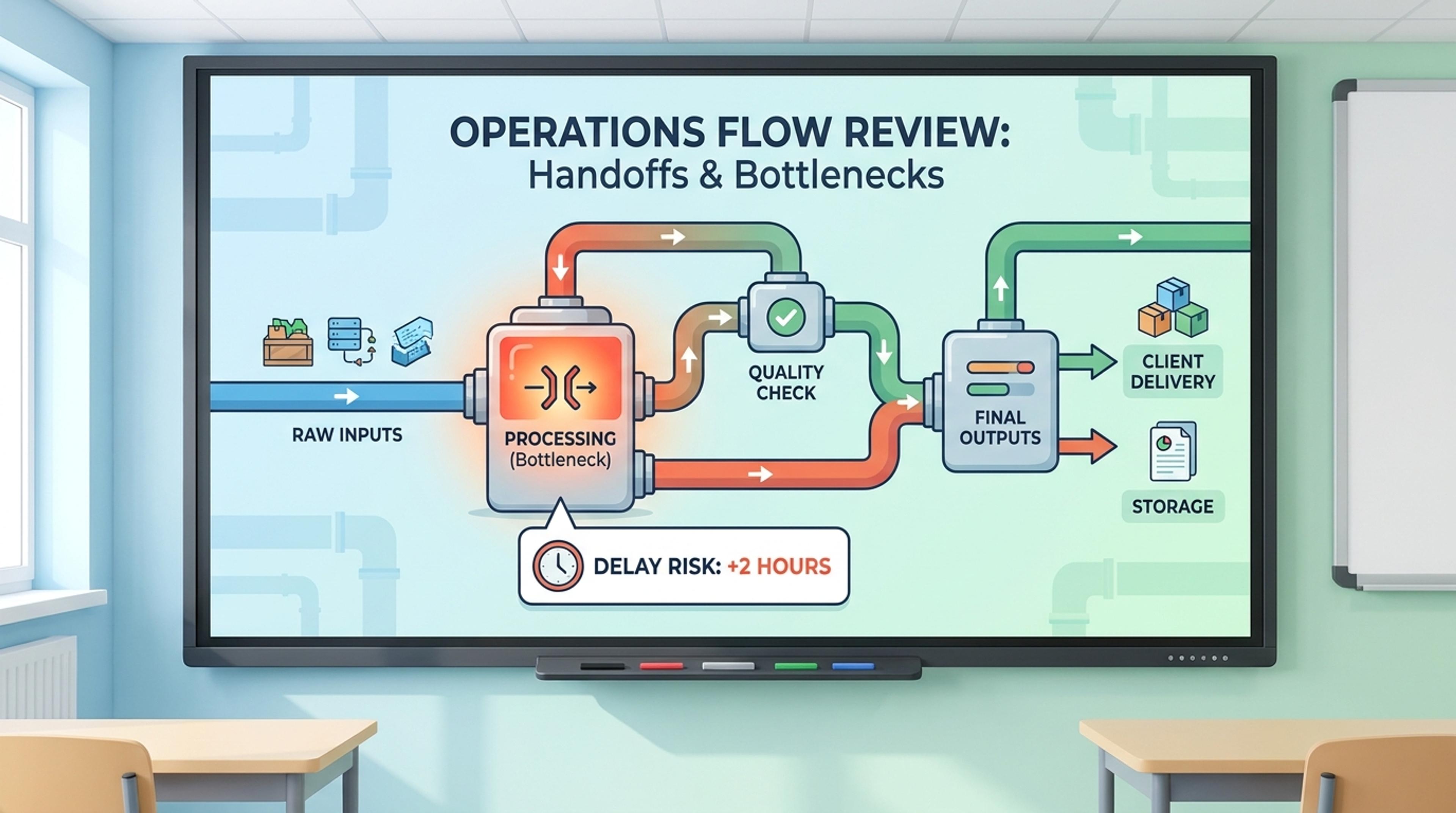
Show handoffs, inputs, outputs, and bottlenecks across a business or production workflow.
Yes. Upload the spec or paste the description and the AI extracts units, junctions, and flow direction without translating away your engineering jargon.
Yes. Each unit becomes a labeled node with optional callouts. Tell the AI which units to emphasize and the layout balances around them.
Yes. Describe the topology — series, parallel, or recirculating — and the diagram routes the segments accordingly without crossing lines.
Yes. Color and group segments by subsystem with a quick prompt. The legend updates automatically.
Export as PNG or JPG for slide decks and PDF for printed engineering reports and training material.
Explore adjacent Infograph tools for circular diagrams, timelines, hierarchy charts, comparisons, and source-to-infographic workflows.
Drop in workflow notes, lifecycle descriptions, or a process doc and Infograph builds a clean circular diagram with directional arrows and balanced phases.
Turn project briefs, history readings, research notes, or links into a clean timeline infographic with milestones, labels, and visual flow.
Upload an org doc, paste a list of teams and roles, or describe the structure in plain English and Infograph builds a clean hierarchy chart.
Drop in feature lists, evaluation docs, or research notes and turn them into a side-by-side comparison chart that reads cleanly in decks and reports.
Paste an article, transcript, or batch of notes and Infograph turns the text into a polished infographic with hierarchy, callouts, and chart treatments.
Upload a research paper, white paper, or report PDF and Infograph extracts the structure to render a clean infographic — no copy-paste between tools.
Turn papers, lab notes, links, text, and data into scientific figures, graphical abstracts, biology diagrams, and research visuals. AI Scientific Figure Maker | Built for research and education